
实验介绍
本实验将通过IPv4地址以及IPv4静态路由的配置来掌握IPv4网络的基本构建与管理。
实验目的
R1、R2和R3互联互通。
拓扑图
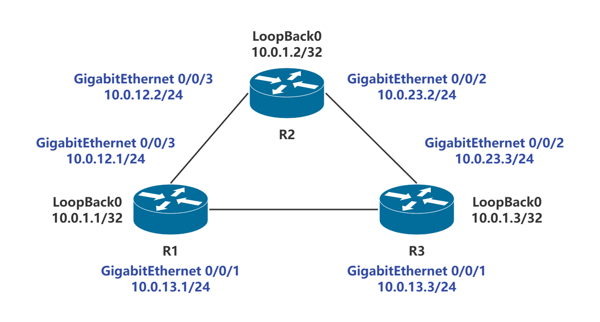
物理接口IP
LoopBack接口
实验步骤
设备命名
<Huawei>system-view
# 进入系统视图
Enter system view, return user view with Ctrl+Z.
[Huawei]sys # sys 按tab键补全
# 重命名
[Huawei]sysname R1
[R1]
R2和R3做相同操作。
配置物理接口IP
[R1]interface GigabitEthernet 0/0/1
# 进入GigabitEthernet 0/0/1接口
[R1-GigabitEthernet0/0/1]ip address 10.0.13.1 24
# 配置IP地址
May  4 2025 19:48:16-08:00 R1 %%01IFNET/4/LINK_STATE(l)[0]:The line protocol IP on the interface GigabitEthernet0/0/1 has entered the UP state.
May  4 2025 19:48:19-08:00 R1 DS/4/DATASYNC_CFGCHANGE:OID 1.3.6.1.4.1.2011.5.25.191.3.1 configurations have been changed. The current change number is 2, the change loop count is 0, and the maximum number of records is 4095.
[R1-GigabitEthernet0/0/1]quit
# 退出
比较快捷的方式
[R1]int g0/0/3
[R1-GigabitEthernet0/0/3]ip a 10.0.12.1 24
# 全程使用简写
## 不建议,还是用tab键补全保险一些
Ping测试
[R1]ping 10.0.13.3
  PING 10.0.13.3: 56  data bytes, press CTRL_C to break
    Reply from 10.0.13.3: bytes=56 Sequence=1 ttl=255 time=70 ms
    Reply from 10.0.13.3: bytes=56 Sequence=2 ttl=255 time=20 ms
    Reply from 10.0.13.3: bytes=56 Sequence=3 ttl=255 time=50 ms
    Reply from 10.0.13.3: bytes=56 Sequence=4 ttl=255 time=20 ms
    Reply from 10.0.13.3: bytes=56 Sequence=5 ttl=255 time=40 ms

  --- 10.0.13.3 ping statistics ---
    5 packet(s) transmitted
    5 packet(s) received
    0.00% packet loss
    round-trip min/avg/max = 20/40/70 ms
查看路由表
[R1]display ip routing-table
Route Flags: R - relay, D - download to fib
------------------------------------------------------------------------------
Routing Tables: Public
         Destinations : 6        Routes : 6

Destination/Mask    Proto   Pre  Cost      Flags NextHop         Interface

      10.0.12.0/24  Direct  0    0           D   10.0.12.1       GigabitEthernet0/0/3
      10.0.12.1/32  Direct  0    0           D   127.0.0.1       GigabitEthernet0/0/3
      10.0.13.0/24  Direct  0    0           D   10.0.13.1       GigabitEthernet0/0/1
      10.0.13.1/32  Direct  0    0           D   127.0.0.1       GigabitEthernet0/0/1
      127.0.0.0/8   Direct  0    0           D   127.0.0.1       InLoopBack0
      127.0.0.1/32  Direct  0    0           D   127.0.0.1       InLoopBack0
配置LoopBack0接口IP
[R1]interface LoopBack 0
[R1-LoopBack0]ip address 10.0.0.1 32
[R1-LoopBack0]
Ping测试
ping-a source-ip-address destination-ip-address 命令用于指定发送 ICMP ECHO-REQUEST 报文的源和目的 IP 地址。由于路由器上没有目的 IP 的路由条目,因此无法 PING 通。
[R1]ping -a 10.0.1.1 10.0.1.3
  PING 10.0.1.3: 56  data bytes, press CTRL_C to break
    Request time out
    Request time out
    Request time out
    Request time out
    Request time out

  --- 10.0.1.3 ping statistics ---
    5 packet(s) transmitted
    0 packet(s) received
    100.00% packet loss
配置静态路由
[R1]ip route-static 10.0.1.2 32 10.0.12.2
[R1]ip route-static 10.0.1.2 32 10.0.12.3
需要在R2和R3上执行相同操作
查看路由表
[R1]dis ip routing-table
Route Flags: R - relay, D - download to fib
------------------------------------------------------------------------------
Routing Tables: Public
         Destinations : 9        Routes : 9

Destination/Mask    Proto   Pre  Cost      Flags NextHop         Interface

       10.0.1.1/32  Direct  0    0           D   127.0.0.1       LoopBack0
       10.0.1.2/32  Static  60   0          RD   10.0.12.2       GigabitEthernet0/0/3
       10.0.1.3/32  Static  60   0          RD   10.0.13.3       GigabitEthernet0/0/1
      10.0.12.0/24  Direct  0    0           D   10.0.12.1       GigabitEthernet0/0/3
      10.0.12.1/32  Direct  0    0           D   127.0.0.1       GigabitEthernet0/0/3
      10.0.13.0/24  Direct  0    0           D   10.0.13.1       GigabitEthernet0/0/1
      10.0.13.1/32  Direct  0    0           D   127.0.0.1       GigabitEthernet0/0/1
      127.0.0.0/8   Direct  0    0           D   127.0.0.1       InLoopBack0
      127.0.0.1/32  Direct  0    0           D   127.0.0.1       InLoopBack0
再次Ping测试
[R1]ping -a 10.0.1.1 10.0.1.2
  PING 10.0.1.2: 56  data bytes, press CTRL_C to break
    Reply from 10.0.1.2: bytes=56 Sequence=1 ttl=255 time=50 ms
    Reply from 10.0.1.2: bytes=56 Sequence=2 ttl=255 time=60 ms
    Reply from 10.0.1.2: bytes=56 Sequence=3 ttl=255 time=10 ms
    Reply from 10.0.1.2: bytes=56 Sequence=4 ttl=255 time=50 ms
    Reply from 10.0.1.2: bytes=56 Sequence=5 ttl=255 time=50 ms

  --- 10.0.1.2 ping statistics ---
    5 packet(s) transmitted
    5 packet(s) received
    0.00% packet loss
    round-trip min/avg/max = 10/44/60 ms
此时R1的LoopBack0已经可以和R2的LoopBack0实现互通。
优先级
静态路由preference(优先级)默认为60 。
优先级默认以小为优。
可用tracert命令查看数据包从源端到目的端的路径信息。
[R1]tracert -a 10.0.1.1 10.0.1.2思考
Q: 什么情况下,配置的静态路由会被添加到IP路由表中?若配置的下一跳不可达,该路由可以被加入到IP路由表吗?
A: 当路由器成功配置该路由且下一跳地址可达时,配置的静态路由会被添加到IP路由表中。如果下一跳不可达,该静态路由将不会被加入到IP路由表,因为路由器无法确定数据包的转发路径。因此,静态路由的有效性依赖于下一跳的可达性。如果下一跳不可达,路由器会忽略该路由配置。
Q: 当测试LoopBack接口之间联通性时,若不加-a参数,则ICMP报文的源IP地址将会是多少?为什么?
A: 当测试Loopback接口之间的连通性时,如果不加-a参数,ICMP报文的源IP地址将是发送方的Loopback接口的IP地址(通常是127.0.0.1)。这是因为Loopback接口是一个虚拟接口,用于自我测试,发送的数据包源自于该接口的IP地址。使用Loopback接口时,系统会自动将源地址设置为该接口的IP,以便进行本地回环测试。