
实验介绍
了解 OSPF 通告缺省路由的方式与原理。
实验目的
R1与R2作为企业边界出口设备,构成双出口冗余以实现负载分担。企业内部部署并运行OSPF路由协议,使Client A与Client B能正常访问 Internet路由器的100.1.1.0网络。为减少路由表容量,在 R1与 R2上配置缺省路由,从而在提供连通性的同时保证网络的高可用性。
拓扑结构
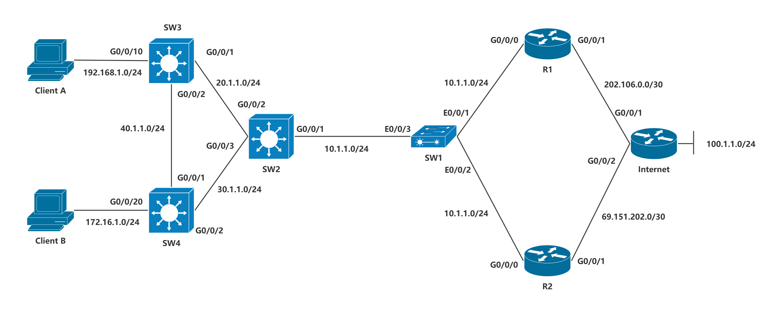
接口信息
实验步骤
步骤一:配置接口IP
SW1为二层交换机,无需额外配置,正常开机即可。
以SW2为例,模拟器的三层交换机无法直接配置接口IP,需要使用VLAN子接口曲线救国。
[SW2-Vlanif1]dis th
#
interface Vlanif1
 ip address 10.1.1.21 255.255.255.0
#
return
[SW2-Vlanif2]dis th
#
interface Vlanif2
 ip address 20.1.1.2 255.255.255.0
#
return
[SW2-Vlanif3]dis th
#
interface Vlanif3
 ip address 30.1.1.2 255.255.255.0
#
return
将端口加进对应VLAN。
VLAN 1默认放行。
[SW2-GigabitEthernet0/0/1]dis th
#
interface GigabitEthernet0/0/1
 port link-type access
#
return
[SW2-GigabitEthernet0/0/2]dis th
#
interface GigabitEthernet0/0/2
 port link-type access
 port default vlan 2
#
return
[SW2-GigabitEthernet0/0/3]di th
#
interface GigabitEthernet0/0/3
 port link-type access
 port default vlan 3
#
return
其余类似,路由器直接在接口配置IP即可。
步骤二:配置NAT
以R1为例。
匹配内部源网段。
[R1-acl-basic-2001]dis th
[V200R003C00]
#
acl number 2001
 rule 5 permit source 192.168.1.0 0.0.0.255
 rule 10 permit source 172.16.1.0 0.0.0.255
#
return
[R1-GigabitEthernet0/0/1]dis th
[V200R003C00]
#
interface GigabitEthernet0/0/1
 ip address 202.106.0.1 255.255.255.252
 nat outbound 2001
#
return
配置缺省路由,指定去往任意网段的下一跳接口IP地址。
[R1]ip route-static 0.0.0.0 0 202.106.0.2步骤三:配置OSPF
R1、R2、SW2、SW3和SW4均需要配置OSPF。
仅R1和R2需要配置OSPF通告缺省路由。
以R1和SW2为例。
[R1-ospf-1]di th
[V200R003C00]
#
ospf 1
 default-route-advertise always cost 10 type 1
 area 0.0.0.0
  network 10.1.1.0 0.0.0.255
#
return
[SW2-ospf-1]dis th
#
ospf 1
 area 0.0.0.0
  network 10.1.1.0 0.0.0.255
  network 20.1.1.0 0.0.0.255
  network 30.1.1.0 0.0.0.255
#
return
通过查看SW2的OSPF路由表项可知,其学习到2条完全等价的缺省路由【O_ASE】
[SW2]display ip routing-table protocol ospf
Route Flags: R - relay, D - download to fib
------------------------------------------------------------------------------
Public routing table : OSPF
         Destinations : 4        Routes : 6

OSPF routing table status : <Active>
         Destinations : 4        Routes : 6

Destination/Mask    Proto   Pre  Cost      Flags NextHop         Interface

        0.0.0.0/0   O_ASE   150  11          D   10.1.1.1        Vlanif1
                    O_ASE   150  11          D   10.1.1.2        Vlanif1
       40.1.1.0/24  OSPF    10   2           D   20.1.1.3        Vlanif2
                    OSPF    10   2           D   30.1.1.4        Vlanif3
     172.16.1.0/24  OSPF    10   2           D   30.1.1.4        Vlanif3
    192.168.1.0/24  OSPF    10   2           D   20.1.1.3        Vlanif2

OSPF routing table status : <Inactive>
         Destinations : 0        Routes : 0
检测客户端到达Internet的Loopback接口的可达性
Welcome to use PC Simulator!

PC>ipconfig

Link local IPv6 address...........: fe80::5689:98ff:fefa:5a5c
IPv6 address......................: :: / 128
IPv6 gateway......................: ::
IPv4 address......................: 192.168.1.1
Subnet mask.......................: 255.255.255.0
Gateway...........................: 192.168.1.3
Physical address..................: 54-89-98-FA-5A-5C
DNS server........................:


PC>ping 100.1.1.1

Ping 100.1.1.1: 32 data bytes, Press Ctrl_C to break
From 100.1.1.1: bytes=32 seq=1 ttl=252 time=62 ms
From 100.1.1.1: bytes=32 seq=2 ttl=252 time=110 ms
From 100.1.1.1: bytes=32 seq=3 ttl=252 time=78 ms
From 100.1.1.1: bytes=32 seq=4 ttl=252 time=94 ms
From 100.1.1.1: bytes=32 seq=5 ttl=252 time=93 ms

--- 100.1.1.1 ping statistics ---
  5 packet(s) transmitted
  5 packet(s) received
  0.00% packet loss
  round-trip min/avg/max = 62/87/110 ms

PC>
Welcome to use PC Simulator!
PC>ipconfig
Link local IPv6 address...........: fe80::5689:98ff:feaf:9f0
IPv6 address......................: :: / 128
IPv6 gateway......................: ::
IPv4 address......................: 172.16.1.1
Subnet mask.......................: 255.255.255.0
Gateway...........................: 172.16.1.4
Physical address..................: 54-89-98-AF-09-F0
DNS server........................:
PC>ping 100.1.1.1
Ping 100.1.1.1: 32 data bytes, Press Ctrl_C to break
From 100.1.1.1: bytes=32 seq=1 ttl=252 time=78 ms
From 100.1.1.1: bytes=32 seq=2 ttl=252 time=78 ms
From 100.1.1.1: bytes=32 seq=3 ttl=252 time=78 ms
From 100.1.1.1: bytes=32 seq=4 ttl=252 time=78 ms
From 100.1.1.1: bytes=32 seq=5 ttl=252 time=94 ms
--- 100.1.1.1 ping statistics ---
5 packet(s) transmitted
5 packet(s) received
0.00% packet loss
round-trip min/avg/max = 78/81/94 ms
PC>注意事项
注1
在使用OSPF VPN实例的环境下,若想要发布指定缺省路由的Type-3 LSA,则需要使用summary参数【无论本机是否存在激活的非本OSPF缺省路由,该参数都将会产生并发布一个描述缺省路由的LSA】
R1:
ospf 1 vpn-instance VPNA
default-route-advertise summary cost 10
注2
在上述案例中,若R1配置的缺省路由的优先级值为200,而R2配置的缺省路由的优先级值为默认的60时,R1与R2各自的路由表项中,都将使用自身所配置的缺省路由
[R1]ip route-static 0.0.0.0 0 202.106.0.2 preference 200
Info: Succeeded in modifying route.
[R1]dis ip routing-table
Route Flags: R - relay, D - download to fib
------------------------------------------------------------------------------
Routing Tables: Public
         Destinations : 16       Routes : 16

Destination/Mask    Proto   Pre  Cost      Flags NextHop         Interface

        0.0.0.0/0   Static  200  0          RD   202.106.0.2     GigabitEthernet0/0/1
       10.1.1.0/24  Direct  0    0           D   10.1.1.1        GigabitEthernet0/0/0
       10.1.1.1/32  Direct  0    0           D   127.0.0.1       GigabitEthernet0/0/0
     10.1.1.255/32  Direct  0    0           D   127.0.0.1       GigabitEthernet0/0/0
       20.1.1.0/24  OSPF    10   2           D   10.1.1.21       GigabitEthernet0/0/0
       30.1.1.0/24  OSPF    10   2           D   10.1.1.21       GigabitEthernet0/0/0
       40.1.1.0/24  OSPF    10   3           D   10.1.1.21       GigabitEthernet0/0/0
      127.0.0.0/8   Direct  0    0           D   127.0.0.1       InLoopBack0
      127.0.0.1/32  Direct  0    0           D   127.0.0.1       InLoopBack0
127.255.255.255/32  Direct  0    0           D   127.0.0.1       InLoopBack0
     172.16.1.0/24  OSPF    10   3           D   10.1.1.21       GigabitEthernet0/0/0
    192.168.1.0/24  OSPF    10   3           D   10.1.1.21       GigabitEthernet0/0/0
    202.106.0.0/30  Direct  0    0           D   202.106.0.1     GigabitEthernet0/0/1
    202.106.0.1/32  Direct  0    0           D   127.0.0.1       GigabitEthernet0/0/1
    202.106.0.3/32  Direct  0    0           D   127.0.0.1       GigabitEthernet0/0/1
255.255.255.255/32  Direct  0    0           D   127.0.0.1       InLoopBack0

[R1]
[R2]dis ip routing-table
Route Flags: R - relay, D - download to fib
------------------------------------------------------------------------------
Routing Tables: Public
         Destinations : 16       Routes : 16

Destination/Mask    Proto   Pre  Cost      Flags NextHop         Interface

        0.0.0.0/0   Static  60   0          RD   69.151.202.2    GigabitEthernet0/0/1
       10.1.1.0/24  Direct  0    0           D   10.1.1.2        GigabitEthernet0/0/0
       10.1.1.2/32  Direct  0    0           D   127.0.0.1       GigabitEthernet0/0/0
     10.1.1.255/32  Direct  0    0           D   127.0.0.1       GigabitEthernet0/0/0
       20.1.1.0/24  OSPF    10   2           D   10.1.1.21       GigabitEthernet0/0/0
       30.1.1.0/24  OSPF    10   2           D   10.1.1.21       GigabitEthernet0/0/0
       40.1.1.0/24  OSPF    10   3           D   10.1.1.21       GigabitEthernet0/0/0
   69.151.202.0/30  Direct  0    0           D   69.151.202.1    GigabitEthernet0/0/1
   69.151.202.1/32  Direct  0    0           D   127.0.0.1       GigabitEthernet0/0/1
   69.151.202.3/32  Direct  0    0           D   127.0.0.1       GigabitEthernet0/0/1
      127.0.0.0/8   Direct  0    0           D   127.0.0.1       InLoopBack0
      127.0.0.1/32  Direct  0    0           D   127.0.0.1       InLoopBack0
127.255.255.255/32  Direct  0    0           D   127.0.0.1       InLoopBack0
     172.16.1.0/24  OSPF    10   3           D   10.1.1.21       GigabitEthernet0/0/0
    192.168.1.0/24  OSPF    10   3           D   10.1.1.21       GigabitEthernet0/0/0
255.255.255.255/32  Direct  0    0           D   127.0.0.1       InLoopBack0
但由于R1与R2自身所配置的缺省路由的优先级值与其通过OSPF发布的缺省路由优先级值无关,因此SW2的OSPF路由表项中,依然存在着2条完全等价的缺省路由
[SW2]dis ip routing-table protocol ospf
Route Flags: R - relay, D - download to fib
------------------------------------------------------------------------------
Public routing table : OSPF
         Destinations : 4        Routes : 6

OSPF routing table status : <Active>
         Destinations : 4        Routes : 6

Destination/Mask    Proto   Pre  Cost      Flags NextHop         Interface

        0.0.0.0/0   O_ASE   150  11          D   10.1.1.1        Vlanif1
                    O_ASE   150  11          D   10.1.1.2        Vlanif1
       40.1.1.0/24  OSPF    10   2           D   30.1.1.4        Vlanif3
                    OSPF    10   2           D   20.1.1.3        Vlanif2
     172.16.1.0/24  OSPF    10   2           D   30.1.1.4        Vlanif3
    192.168.1.0/24  OSPF    10   2           D   20.1.1.3        Vlanif2

OSPF routing table status : <Inactive>
         Destinations : 0        Routes : 0
此时,若希望SW2将R2发布的缺省路由作为主路由,则需要在R1的OSPF 进程下发布缺省路由时,使用【permit-calculate-other】参数
permit-calculate-other 配置允许在本机存在激活的非本OSPF缺省路由时,将会产生并发布一个缺省路由的LSA,且当前设备仍然计算来自于其它设备的缺省路由
R1:
ospf 1
default-route-advertise permit-calculate-other
再次查看R1的路由表项,发现 RT1此时已经使用R2【10.1.1.2】通过OSPF发布的优先级值为150的缺省路由
~SW2的OSPF路由表项中,此时也只存在1条由R2【10.1.1.2】所发布的缺省路由
[SW2]dis ip routing-table protocol ospf
Route Flags: R - relay, D - download to fib
------------------------------------------------------------------------------
Public routing table : OSPF
         Destinations : 4        Routes : 5

OSPF routing table status : <Active>
         Destinations : 4        Routes : 5

Destination/Mask    Proto   Pre  Cost      Flags NextHop         Interface

        0.0.0.0/0   O_ASE   150  11          D   10.1.1.2        Vlanif1
       40.1.1.0/24  OSPF    10   2           D   30.1.1.4        Vlanif3
                    OSPF    10   2           D   20.1.1.3        Vlanif2
     172.16.1.0/24  OSPF    10   2           D   30.1.1.4        Vlanif3
    192.168.1.0/24  OSPF    10   2           D   20.1.1.3        Vlanif2

OSPF routing table status : <Inactive>
         Destinations : 0        Routes : 0
注3
在上述案例中,若希望SW2从R1学习到的缺省路由带有标记5,而从R2学习到的缺省路由带有标记7,则需要使用【route-policy】参数
route-policy easthome permit node 10创建路由策略,并定义为允许策略,序列号为10
apply tag 5 配置其标记为5
default-route-advertise route-policy easthome cost 10 type 1 配置在路由表中有匹配的非OSPF产生的缺省路 由表项时,按策略发布缺省路由,并设置其代价值为10,且以外部类型1的方式进行发布
RTA:
route-policy R1 permit node 10
apply tag 5
ospf 1
default-route-advertise route-policy R1 cost 10 type 1
RTB:
route-policy R2 permit node 10
apply tag 7
ospf 1
default-route-advertise route-policy R2 cost 10 type 1在SWB上查看其OSPF路由表项的详细信息
[SW2]dis ip routing-table protocol ospf verbose
Route Flags: R - relay, D - download to fib
------------------------------------------------------------------------------
Routing Tables: Public
         Destinations : 4        Routes : 6


Destination: 0.0.0.0/0
     Protocol: O_ASE           Process ID: 1
   Preference: 150                   Cost: 11
      NextHop: 10.1.1.1         Neighbour: 0.0.0.0
        State: Active Adv             Age: 00h01m14s
          Tag: 5                 Priority: low
        Label: NULL               QoSInfo: 0x0
   IndirectID: 0x0
 RelayNextHop: 0.0.0.0          Interface: Vlanif1
     TunnelID: 0x0                  Flags:  D

Destination: 0.0.0.0/0
     Protocol: O_ASE           Process ID: 1
   Preference: 150                   Cost: 11
      NextHop: 10.1.1.2         Neighbour: 0.0.0.0
        State: Active Adv             Age: 00h00m28s
          Tag: 7                 Priority: low
        Label: NULL               QoSInfo: 0x0
   IndirectID: 0x0
 RelayNextHop: 0.0.0.0          Interface: Vlanif1
     TunnelID: 0x0                  Flags:  D

Destination: 40.1.1.0/24
     Protocol: OSPF            Process ID: 1
   Preference: 10                    Cost: 2
      NextHop: 30.1.1.4         Neighbour: 0.0.0.0
        State: Active Adv             Age: 00h48m17s
          Tag: 0                 Priority: low
        Label: NULL               QoSInfo: 0x0
   IndirectID: 0x0
 RelayNextHop: 0.0.0.0          Interface: Vlanif3
     TunnelID: 0x0                  Flags:  D

Destination: 40.1.1.0/24
     Protocol: OSPF            Process ID: 1
   Preference: 10                    Cost: 2
      NextHop: 20.1.1.3         Neighbour: 0.0.0.0
        State: Active Adv             Age: 00h43m44s
          Tag: 0                 Priority: low
        Label: NULL               QoSInfo: 0x0
   IndirectID: 0x0
 RelayNextHop: 0.0.0.0          Interface: Vlanif2
     TunnelID: 0x0                  Flags:  D

Destination: 172.16.1.0/24
     Protocol: OSPF            Process ID: 1
   Preference: 10                    Cost: 2
      NextHop: 30.1.1.4         Neighbour: 0.0.0.0
        State: Active Adv             Age: 00h48m06s
          Tag: 0                 Priority: low
        Label: NULL               QoSInfo: 0x0
   IndirectID: 0x0
 RelayNextHop: 0.0.0.0          Interface: Vlanif3
     TunnelID: 0x0                  Flags:  D

Destination: 192.168.1.0/24
     Protocol: OSPF            Process ID: 1
   Preference: 10                    Cost: 2
      NextHop: 20.1.1.3         Neighbour: 0.0.0.0
        State: Active Adv             Age: 00h52m49s
          Tag: 0                 Priority: low
        Label: NULL               QoSInfo: 0x0
   IndirectID: 0x0
 RelayNextHop: 0.0.0.0          Interface: Vlanif2
     TunnelID: 0x0                  Flags:  D
通过查看可知,SW2通过10.1.1.1【R1】学习到的缺省路由所携带的标记值为5,而通过10.1.1.2【R2】学习到的缺省路由所携带的标记值为7
注4
【match-any】参数指定OSPF路由表中有匹配的路由表项时【无论是否是OSPF产生的缺省路由】,若有多条路由通过策略,则选取最优者来生成缺省LSA;路由通过策略时,选取最优者的原则按照优先级由高至低的顺序如下:
-
路由设置了
Type的优先于未设置的,若均设置了Type,则数值越小越优选; -
路由设置了
Cost的优先于未设置的,若均设置了Cost,则数值越小越优选; -
路由设置了
Tag的优先于未设置的,若均设置了Tag,则数值越小越优选