
实验介绍
访问控制列表(ACL,Access Control List)由一系列规则组成。每条规则是描述报文匹配条件的判断语句,这些条件可以包括源地址、目的地址、端口号等。ACL 本质上是一种报文过滤器,规则则相当于过滤器的滤芯。设备根据这些规则对报文进行匹配,从而筛选出符合条件的报文,并根据应用ACL的业务模块的处理策略,决定是否允许或阻止这些报文通过。
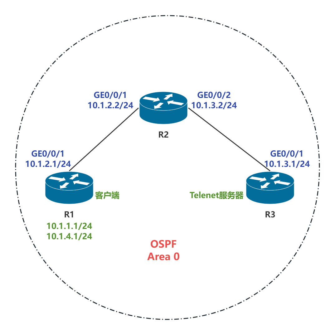
如组网图所示,R3 作为服务器,R1 作为客户端,客户端与服务器之间的路由是可达的。R1 与 R2 之间的互联物理接口地址分别为 10.1.2.1/24 和 10.1.2.2/24,R2 与 R3 之间的互联物理接口地址分别为 10.1.3.2/24 和 10.1.3.1/24。此外,R1 上创建了两个逻辑接口 LoopBack 0 和 LoopBack 1,分别模拟两个客户端用户,地址为 10.1.1.1/24 和 10.1.4.1/24。其中,R1 的 LoopBack 1 接口对应的用户需要远程管理设备 R3,可在服务器端配置 Telnet 服务,用户通过密码登录,并结合基于 ACL 的安全策略,确保只有符合安全策略的用户能够访问设备。
实验目的
-
掌握 ACL 的配置方法
-
掌握 ACL 在接口下的应用方法
-
掌握流量过滤的基本方式
拓扑结构
接口信息
实验步骤
步骤一:配置设备 IP 地址
配置R1、R2和R3的IP地址
在R1上:
[R1-GigabitEthernet0/0/1]dis th
[V200R003C00]
#
interface GigabitEthernet0/0/1
 ip address 10.1.2.1 255.255.255.0
#
[R1-LoopBack0]dis th
[V200R003C00]
#
interface LoopBack0
ip address 10.1.1.1 255.255.255.0
#
return[R1-LoopBack1]dis th
[V200R003C00]
#
interface LoopBack1
ip address 10.1.4.1 255.255.255.0
#
return在R2上:
[R2-GigabitEthernet0/0/1]dis th
[V200R003C00]
#
interface GigabitEthernet0/0/1
 ip address 10.1.2.2 255.255.255.0
#
return
[R2-GigabitEthernet0/0/2]dis th
[V200R003C00]
#
interface GigabitEthernet0/0/2
ip address 10.1.3.2 255.255.255.0
#
return在R3上:
[R3-GigabitEthernet0/0/1]dis th
[V200R003C00]
#
interface GigabitEthernet0/0/1
 ip address 10.1.3.1 255.255.255.0
#
return
步骤二:配置OSPF使网络互通
在R1、R2和R3上配置OSPF,三台设备均在区域0中,实现全网互联互通
在R1上:
[R1-ospf-1]dis th
[V200R003C00]
#
ospf 1
 area 0.0.0.0
  network 10.1.2.1 0.0.0.0
  network 10.1.4.1 0.0.0.0
  network 100.1.1.1 0.0.0.0
#
return
在R2上:
[R2-ospf-1]dis th
[V200R003C00]
#
ospf 1
 area 0.0.0.0
  network 10.1.2.2 0.0.0.0
  network 10.1.3.2 0.0.0.0
#
return
在R3上:
[V200R003C00]
#
ospf 1
 area 0.0.0.0
  network 10.1.3.1 0.0.0.0
#
return
OSPF验证:
[R1]dis ospf p b

         OSPF Process 1 with Router ID 10.1.2.1
                  Peer Statistic Information
 ----------------------------------------------------------------------------
 Area Id          Interface                        Neighbor id      State
 0.0.0.0          GigabitEthernet0/0/1             10.1.2.2         Full
 ----------------------------------------------------------------------------
[R1]
[R2]dis ospf p b
OSPF Process 1 with Router ID 10.1.2.2
Peer Statistic Information
----------------------------------------------------------------------------
Area Id Interface Neighbor id State
0.0.0.0 GigabitEthernet0/0/1 10.1.2.1 Full
0.0.0.0 GigabitEthernet0/0/2 10.1.3.1 Full
----------------------------------------------------------------------------
[R2][R3]dis ospf p b
OSPF Process 1 with Router ID 10.1.3.1
Peer Statistic Information
----------------------------------------------------------------------------
Area Id Interface Neighbor id State
0.0.0.0 GigabitEthernet0/0/1 10.1.2.2 Full
----------------------------------------------------------------------------
[R3]在R3上执行Ping命令,检测网络的连通性
[R3]ping 10.1.1.1
  PING 10.1.1.1: 56  data bytes, press CTRL_C to break
    Reply from 10.1.1.1: bytes=56 Sequence=1 ttl=254 time=40 ms
    Reply from 10.1.1.1: bytes=56 Sequence=2 ttl=254 time=40 ms
    Reply from 10.1.1.1: bytes=56 Sequence=3 ttl=254 time=40 ms
    Reply from 10.1.1.1: bytes=56 Sequence=4 ttl=254 time=40 ms
    Reply from 10.1.1.1: bytes=56 Sequence=5 ttl=254 time=40 ms

  --- 10.1.1.1 ping statistics ---
    5 packet(s) transmitted
    5 packet(s) received
    0.00% packet loss
    round-trip min/avg/max = 40/40/40 ms
[R3]ping 10.1.2.1
  PING 10.1.2.1: 56  data bytes, press CTRL_C to break
    Reply from 10.1.2.1: bytes=56 Sequence=1 ttl=254 time=50 ms
    Reply from 10.1.2.1: bytes=56 Sequence=2 ttl=254 time=40 ms
    Reply from 10.1.2.1: bytes=56 Sequence=3 ttl=254 time=40 ms
    Reply from 10.1.2.1: bytes=56 Sequence=4 ttl=254 time=30 ms
    Reply from 10.1.2.1: bytes=56 Sequence=5 ttl=254 time=40 ms

  --- 10.1.2.1 ping statistics ---
    5 packet(s) transmitted
    5 packet(s) received
    0.00% packet loss
    round-trip min/avg/max = 30/40/50 ms
[R3]ping 10.1.4.1
  PING 10.1.4.1: 56  data bytes, press CTRL_C to break
    Reply from 10.1.4.1: bytes=56 Sequence=1 ttl=254 time=40 ms
    Reply from 10.1.4.1: bytes=56 Sequence=2 ttl=254 time=40 ms
    Reply from 10.1.4.1: bytes=56 Sequence=3 ttl=254 time=30 ms
    Reply from 10.1.4.1: bytes=56 Sequence=4 ttl=254 time=50 ms
    Reply from 10.1.4.1: bytes=56 Sequence=5 ttl=254 time=40 ms

  --- 10.1.4.1 ping statistics ---
    5 packet(s) transmitted
    5 packet(s) received
    0.00% packet loss
    round-trip min/avg/max = 30/40/50 ms
步骤三:配置R3为Telnet服务器
在R3使能Telnet功能,配置用户权限等级为3级,登录密码为Huawei@123
[R3]tel s en
 Error: TELNET server has been enabled
telnet server enable命令用来使能Telnet服务器。
[R3]user-int vty 0 4
VTY(Virtual Terminal)用户界面,用于管理和监控通过Telnet或SSH协议登录的用户。
[R3-ui-vty0-4]user pri l 3
[R3-ui-vty0-4]set au pass cip Huawei@123
[R3-ui-vty0-4]dis th
[V200R003C00]
#
user-interface con 0
 authentication-mode password
 idle-timeout 0 0
user-interface vty 0 4
 authentication-mode password
 user privilege level 3
 set authentication password cipher %$%$bP>%'E8*Z!|''[Ef^j&.,#QNZ|rt~}OeAKNEvlQ="Y.C#QQ,%$%$
user-interface vty 16 20
#
return
步骤四:配置ACL进行流量过滤
方式一:在R3的VTY接口匹配ACL,允许R1通过LoopBack1口地址Telnet到R3。
在R3上配置ACL
[R3-acl-adv-3000]dis th
[V200R003C00]
#
acl number 3000
 rule 5 permit tcp source 10.1.4.1 0 destination 10.1.3.1 0 destination-port eq telnet
 rule 10 deny tcp
#
return
在R3的VTY接口上进行流量过滤
[R3]user-int vty 0 4
[R3-ui-vty0-4]acl 3000 inbound
在R3上查看ACL配置信息
[R3]dis acl 3000
Advanced ACL 3000, 2 rules
Acl's step is 5
 rule 5 permit tcp source 10.1.4.1 0 destination 10.1.3.1 0 destination-port eq telnet
 rule 10 deny tcp
display acl 命令用来查看ACL的配置信息。
ACL 的步长为5。
规则5,允许特定的流量通过,当没有匹配的报文时,不显示matches字段。
方式二:在R2的物理接口匹配ACL,只允许R1通过物理接口地址Telnet到R3。
在R2上配置ACL
[R2-acl-adv-3001]dis th
[V200R003C00]
#
acl number 3001
 rule 5 permit tcp source 10.1.4.1 0 destination 10.1.3.1 0 destination-port eq telnet
 rule 10 deny tcp
#
return
在R2的GE0/0/1接口上进行流量过滤
[R2-GigabitEthernet0/0/1]dis th
[V200R003C00]
#
interface GigabitEthernet0/0/1
 ip address 10.1.2.2 255.255.255.0
 traffic-filter inbound acl 3001
#
return
在R2上查看ACL配置信息
[R2]dis acl 3001
Advanced ACL 3001, 2 rules
Acl's step is 5
 rule 5 permit tcp source 10.1.4.1 0 destination 10.1.3.1 0 destination-port eq telnet
 rule 10 deny tcp
规则5,允许特定的流量通过。
结果验证
检测Telnet访问,验证ACL配置结果
在R1上带源地址10.1.1.1 telnet 到服务器。
<R1>tel -a 10.1.1.1 10.1.3.1
  Press CTRL_] to quit telnet mode
  Trying 10.1.3.1 ...
  Error: Can't connect to the remote host
telnet命令用来从当前设备使用Telnet协议登录到其它设备。
- a source-ip-address:通过指定源地址,用户可以用指定的IP地址与服务端通信。
在R1上带源地址10.1.4.1 telnet 到服务器。
<R1>tel -a 10.1.4.1 10.1.3.1
  Press CTRL_] to quit telnet mode
  Trying 10.1.3.1 ...
  Connected to 10.1.3.1 ...

Login authentication


Password:
<R3>quit

  Configuration console exit, please retry to log on

  The connection was closed by the remote host
<R1>